As I continued the descent into my split keyboard addiction, I decided to dive off the deep end and handwire my own ergonomic keyboard.
My Corne was a good intro keyboard, but I eventually determined it had more keys than I actually needed. I also grew intrigued towards keyboards with better ergonomics - more stagger and splay to improve alignment with ring and pinky fingers, as well as keyboards with sculpted, organic surfaces to better follow my hand’s natural shape.
Other keyboards like the Charybdis seemed to be quite popular, but I was searching for something smaller and less bulky looking. I also didn’t want to design my own using Cosmos just yet, since I knew it’d take a few iterations to get right which would be difficult without my own 3D printer.
The Skeletyl spoke to me on an spiritual level, and although it lacked an integrated pointing device like a trackpoint, it checked enough boxes for me to be sold on that form factor.
Since I had never used a keyboard like this before, I was hesitant to put too much money into it. Prebuilt options and kits were going for >$300 CAD, which was more than I was willing to empty my wallet for something that might just be a fad for me. Although I could have tried sourcing the PCBs myself, this keyboard was a perfect candidate to try handwiring due to its complex shape as well as keeping costs low since I had most of the equipment already.
So with my soldering iron and wires in hand, I began my quest.
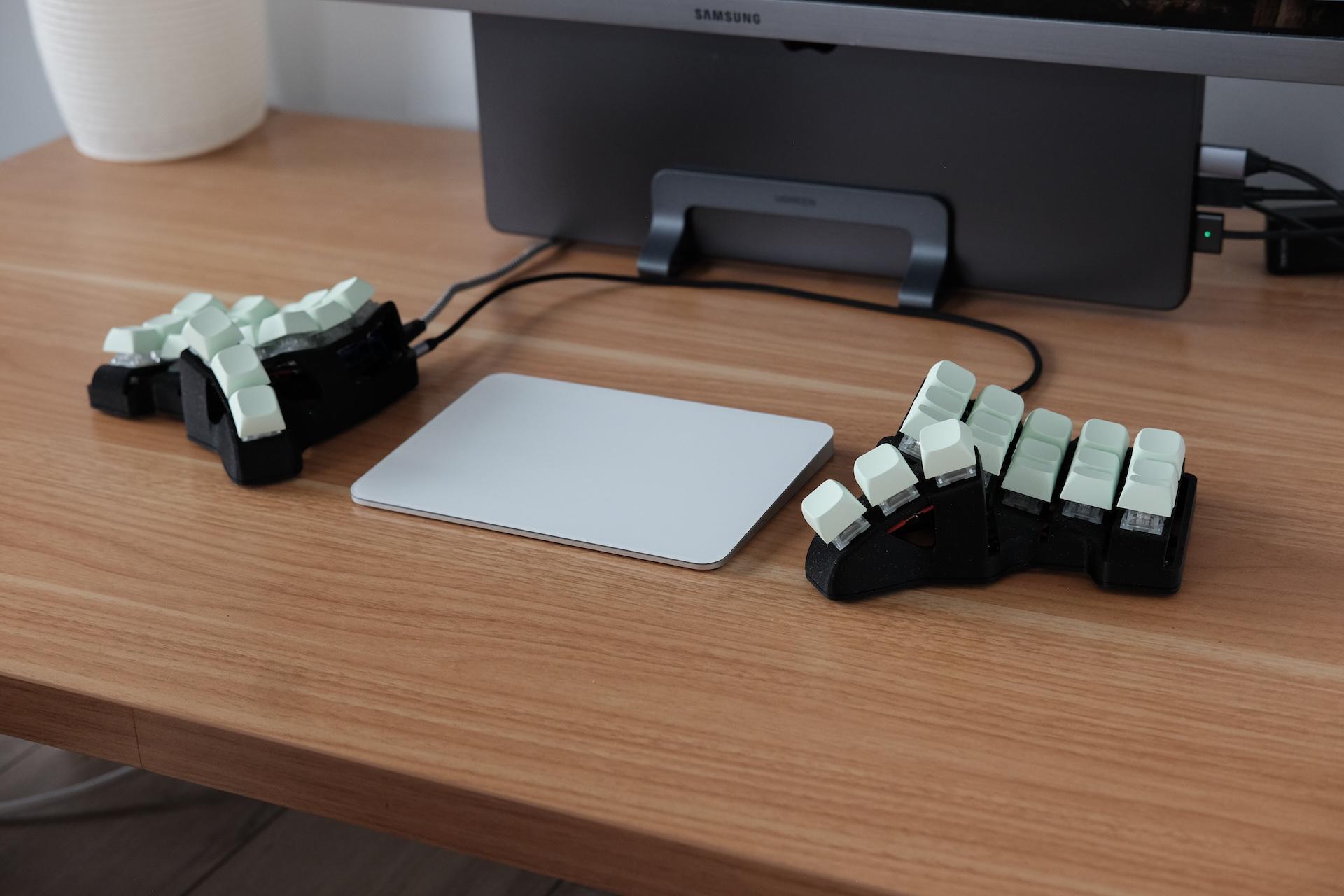
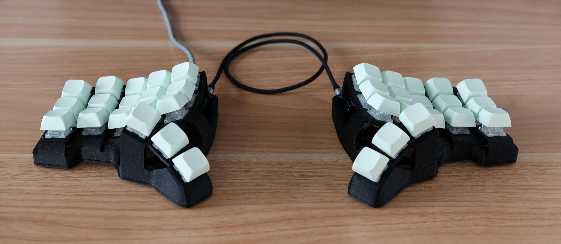
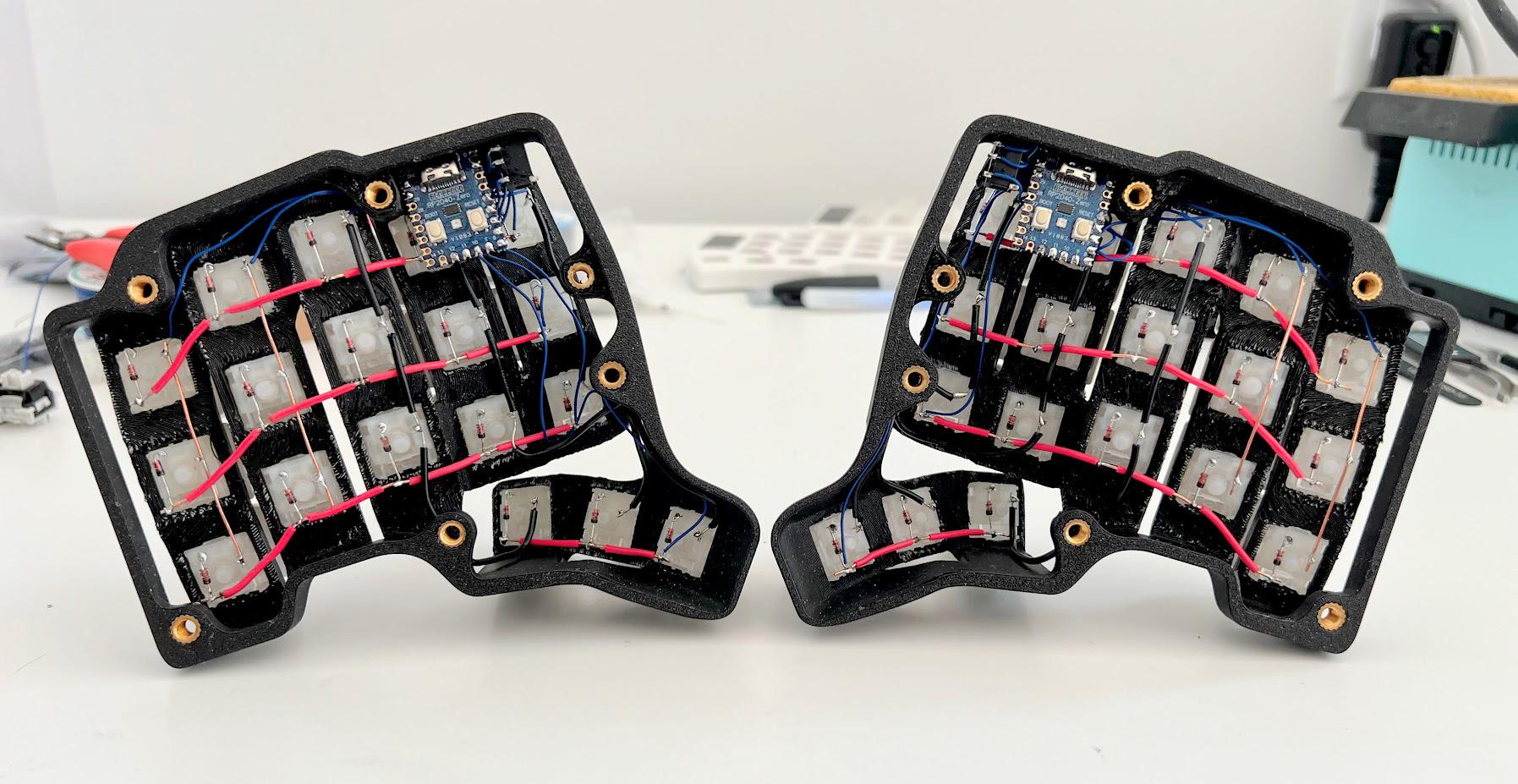
The completed Skeletyl in its natural habitat.
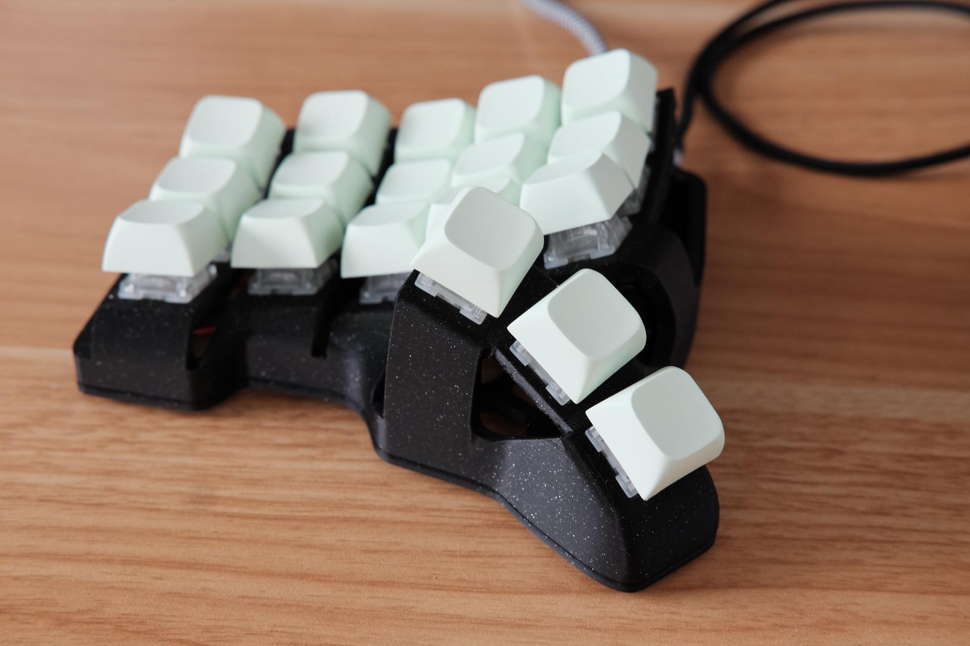
Close up of the left half. The sparkle pattern came through quite well!
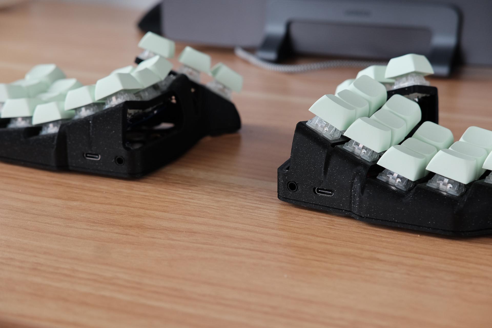
Backside of the keyboard showing the USB-C and TRS ports.
The Build
Bill of Materials
My friend from Ember Prototypes was kind enough to print the case for me, but if you don’t have access to a 3D printer yourself or a friend who does, many local libraries have them and are usually very affordable. Otherwise, places like JLCPCB offer printing for not too much.
Total cost for my build was ~$70 CAD, where $45 of it was from the keycaps and (relatively expensive) switches. Aside from the case, all parts were sourced from Amazon and Aliexpress.
If you’re looking to build one yourself, based on the parts I found it can range from $45-100 CAD. Getting the build to be <$40 would likely be possible if you hunt a bit harder for better deals, especially since switches and keycaps make up for a large portion of the overall cost. Alternatively, 3D printing your own keycaps is an option to further save some money.
For my build, I chose the same TTC Frozen Silent v2 switches that I used on my Corne keyboard, and I bought blank PBT in the XDA profile. I tried Cherry/OEM profile, but I wasn’t a fan of feel or look of the sharp corners.
| Part | Quantity | Cost (in CAD) |
|---|---|---|
| 3D printed case (top + bottom) | 2 | $0-15 |
| M4 heat-set threaded inserts | 12 | $2 |
| M4 5mm fasteners | 12 | $3 |
| 1N4148 diodes (through hole) | 36 | $1 |
| TRS/TRRS connectors | 2 | $3 |
| RP2040 Zero dev board | 2 | $12 |
| TRS cable | 1 | $4 |
| MX switches | 36 | $5-30 |
| MX-compatible keycaps | 36 | $15-30 |
Schematic
The wiring followed a basic row/column matrix, where the diodes were connected along the rows, and the remaining switch legs were wired directly together in columns.
On the MCU, the pins required were:
- Switch matrix, 4 rows x 5 columns = 9 GPIO pins
- TRS connector (soft serial) = 1 GPIO pin, VCC, GND
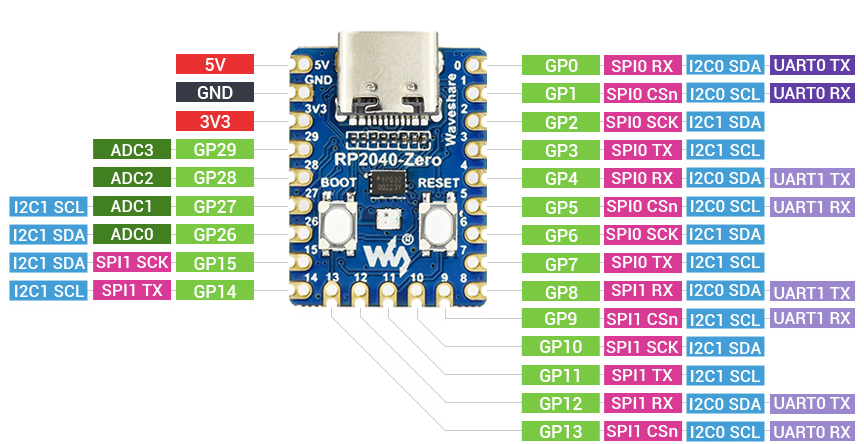
RP2040 Pinout. (Source: Waveshare)
In order for both sides to communicate with each other, there are a few different ways that QMK supports. I opted for the simplest of using soft serial so only three wires were required. For the RP2040, the soft serial pin (using the PIO driver) needed to be GP1.
For the matrix columns and rows, I chose the pins on the right side to make it a bit easier to assemble. Any valid pins can be used, as long as they’re mapped correctly in the QMK keyboard.json, where mine looks something like this (full configuration below).
	...
    "matrix_pins": {
        "cols": ["GP4", "GP5", "GP6", "GP7", "GP8"],
        "rows": ["GP9", "GP10", "GP11", "GP12"]
    },
    "split": {
		...
        "soft_serial_pin": "GP1",
        "matrix_pins": {
            "right": {
                "cols": ["GP8", "GP7", "GP6", "GP5", "GP4"],
                "rows": ["GP9", "GP10", "GP11", "GP12"]
            }
        }
    },
	...
Assembling the Hardware
Despite having quite a bit of soldering experience, handwiring still took longer than expected - the first half took about 3-4h, and the second half took maybe 2-3h once I figured out the best way to do certain things. It seems like such a simple task of just connecting wires together, but as with most things, it still takes time and effort. Though it did turn out to be a pleasant change of pace to my typical programming work, since the manual, dexterous, but not cognitively-challenging labour required a different type of patience that ended up being a bit meditative.
The models for the case (without the additional tenting) were downloaded from Printables, and was printed on a Bambu Lab P1S in the Onyx Black PLA Sparkle.
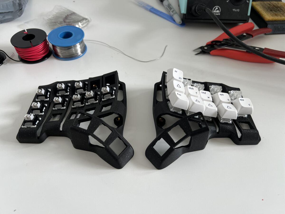
Test fitting the switches and a few keycaps to get a sense of how the sculpted profile feels.
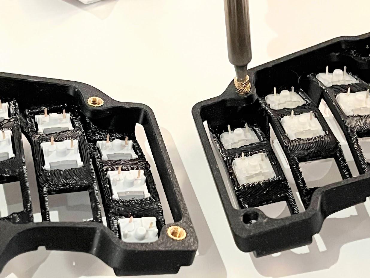
Using a soldering iron to install the heatset inserts.
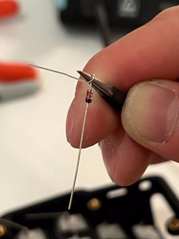
Coiling the diode leg to make it easier to attach to the switch pin.
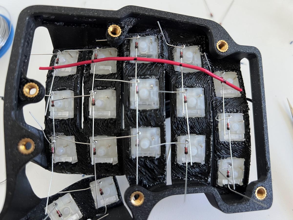
Diodes placed, marking the wire locations to splice.
For splicing the wire, this turned out to be easier to do than expected. Joe Scotto’s way is to use bare copper wire and heat shrink the intersections, but I didn’t think it was actually that much faster since it still takes time to cut, place, and heat the heat shrink.
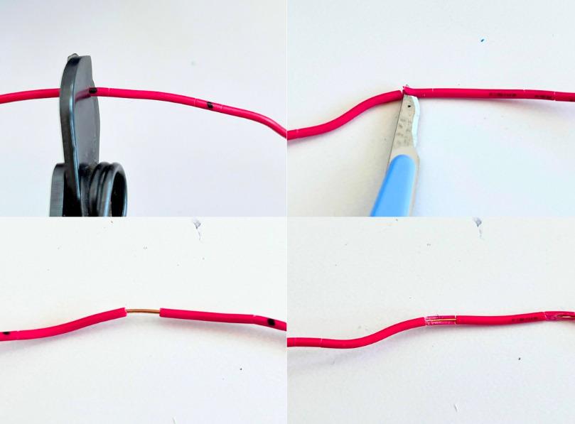
Using basic wire cutters and an x-acto knife to expose the wire.
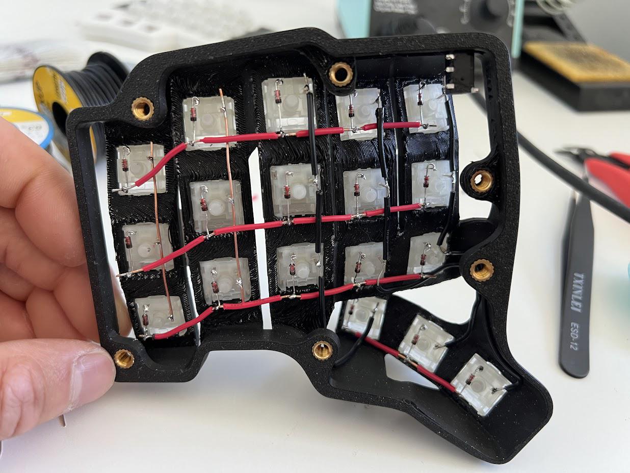
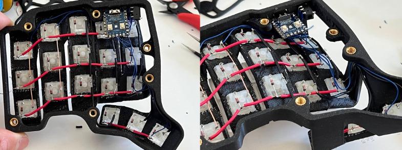
Rows and columns all connected!
One weird aspect of sculpted keyboards is how the thumb clusters are on a different plane than the rest of the keys. The wiring ended up looking a little funny, but I wanted to hide it reasonably well to prevent them peeking through the exposed sections of the case.
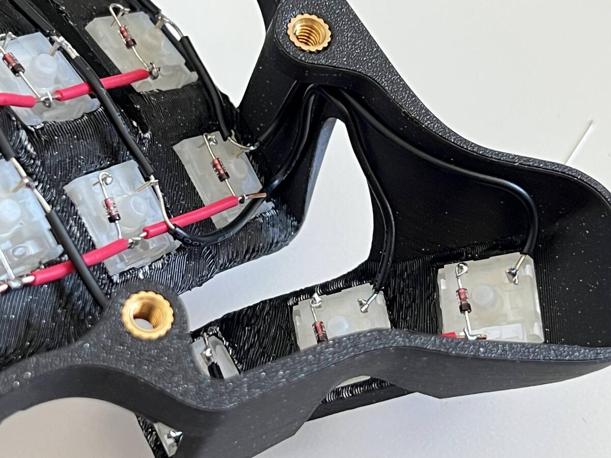
Close up of how I wired the thumb cluster keys.
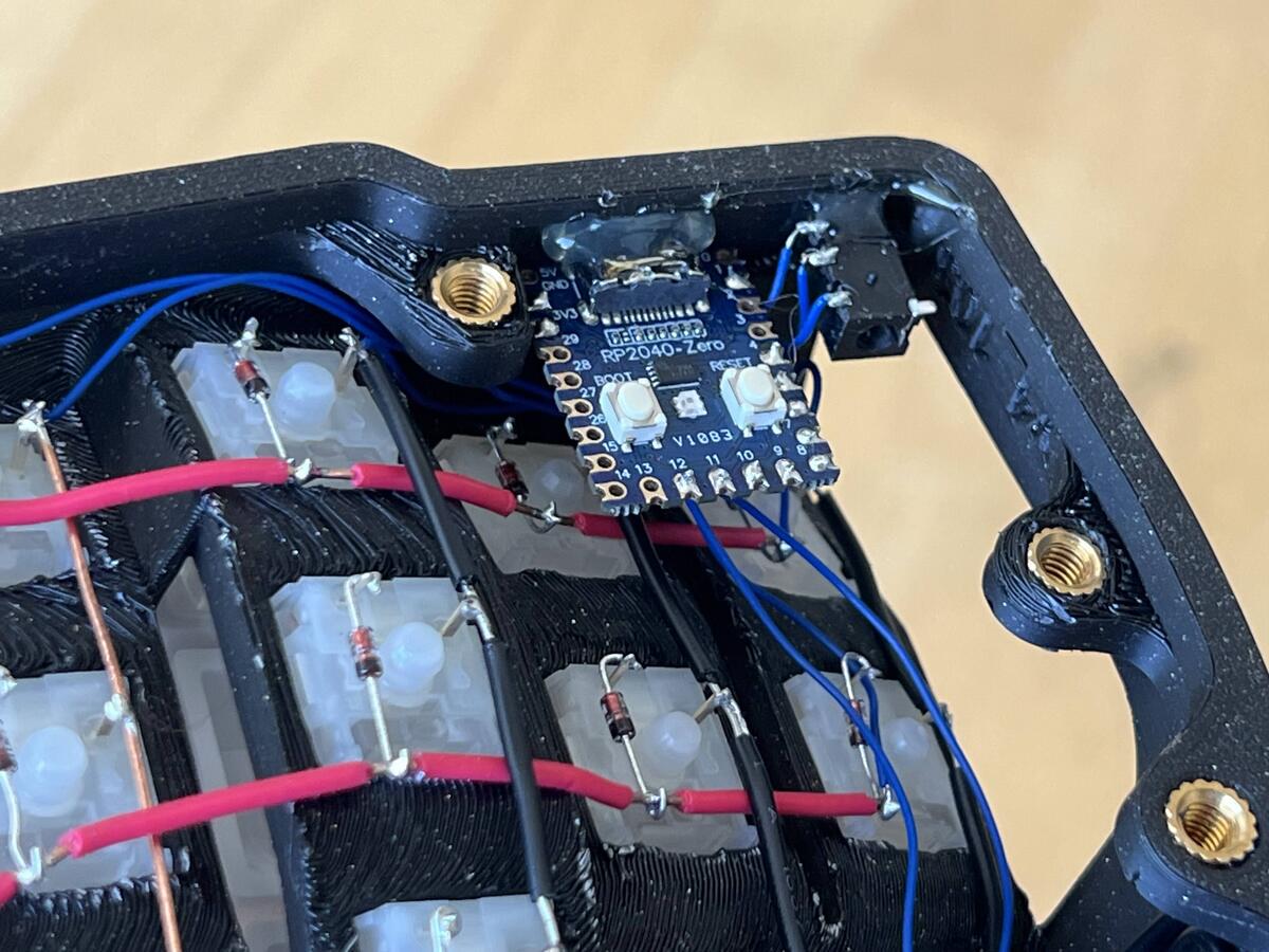
With the matrix all done, all that was left was to wire each row and column to the MCU. I chose to solder these blue wires at the ends of each row and column to keep things looking tidy. The MCU was oriented upside down so the reset buttons would still be easily accessible when fully assembled.
For the TRS connector, I initially bought ones on breakout boards, but it turned out to be way too bulky so I had to desolder it. Was a bit of a pain, but it worked out in the end.
RP2040-Zero all wired up.
Doing everything again for the other half, and it was complete!
Build complete!
I initially thought to design a nice 3D printed bracket to hold the MCU and TRS connector, but I was impatient and opted for the hacky way of just using hot glue since I was likely only going to be building this once.
Surprisingly, the glue was sturdy enough to hold the components in place even when plugging/unplugging the cables from them.
Securing components with “structural” hot glue.
Compiling the Firmware
QMK
I followed the QMK tutorial and forked the repo, ran the new keyboard command, and then updated the config. With the RP2040, the bootloader and processor needed to just be RP2040 instead of the dev board, which was one of the default options.
It took a while to figure out what the correct configuration was for the layout, but I eventually got it done with a bit of help from ChatGPT.
For the firmware flashing, I just set the split enabled flag for each side and commented out the opposite side. Maybe next time I’ll use EEPROM or setting a pin high to avoid needing to build different firmware for each side.
#pragma once

/* RP2040- and hardware-specific config */
#define RP2040_BOOTLOADER_DOUBLE_TAP_RESET // Activates the double-tap behavior
#define RP2040_BOOTLOADER_DOUBLE_TAP_RESET_TIMEOUT 500U
#define PICO_XOSC_STARTUP_DELAY_MULTIPLIER 64

#define SERIAL_PIO_USE_PIO1
In rules.mk:
SERIAL_DRIVER = vendor
And the keyboard.json:
{
    "manufacturer": "Justin Lam",
    "keyboard_name": "skeletyl",
    "maintainer": "Justin Lam",
    "bootloader": "rp2040",
    "processor": "RP2040",
    "diode_direction": "COL2ROW",
    "features": {
        "bootmagic": false,
        "extrakey": false,
        "mousekey": true,
        "nkro": false
    },
    "matrix_pins": {
        "cols": ["GP4", "GP5", "GP6", "GP7", "GP8"],
        "rows": ["GP9", "GP10", "GP11", "GP12"]
    },
    "split": {
        "enabled": true,
        "main": "right",
        "soft_serial_pin": "GP1",
        "transport": { "protocol": "serial" },
        "matrix_pins": {
            "right": {
                "cols": ["GP8", "GP7", "GP6", "GP5", "GP4"],
                "rows": ["GP9", "GP10", "GP11", "GP12"]
            }
        }
    },
    "url": "...",
    "usb": {
        "device_version": "1.0.0",
        "pid": "0x0254",
        "vid": "0xFEED"
    },
    "layouts": {
        "LAYOUT_split_3x5_3": {
            "layout": [
                {"matrix": [0, 0], "x": 0, "y": 0.25},
                {"matrix": [0, 1], "x": 1, "y": 0.125},
                {"matrix": [0, 2], "x": 2, "y": 0},
                {"matrix": [0, 3], "x": 3, "y": 0.125},
                {"matrix": [0, 4], "x": 4, "y": 0.25},
                {"matrix": [4, 0], "x": 7, "y": 0.25},
                {"matrix": [4, 1], "x": 8, "y": 0.125},
                {"matrix": [4, 2], "x": 9, "y": 0},
                {"matrix": [4, 3], "x": 10, "y": 0.125},
                {"matrix": [4, 4], "x": 11, "y": 0.25},
                {"matrix": [1, 0], "x": 0, "y": 1.25},
                {"matrix": [1, 1], "x": 1, "y": 1.125},
                {"matrix": [1, 2], "x": 2, "y": 1},
                {"matrix": [1, 3], "x": 3, "y": 1.125},
                {"matrix": [1, 4], "x": 4, "y": 1.25},
                {"matrix": [5, 0], "x": 7, "y": 1.25},
                {"matrix": [5, 1], "x": 8, "y": 1.125},
                {"matrix": [5, 2], "x": 9, "y": 1},
                {"matrix": [5, 3], "x": 10, "y": 1.125},
                {"matrix": [5, 4], "x": 11, "y": 1.25},
                {"matrix": [2, 0], "x": 0, "y": 2.25},
                {"matrix": [2, 1], "x": 1, "y": 2.125},
                {"matrix": [2, 2], "x": 2, "y": 2},
                {"matrix": [2, 3], "x": 3, "y": 2.125},
                {"matrix": [2, 4], "x": 4, "y": 2.25},
                {"matrix": [6, 0], "x": 7, "y": 2.25},
                {"matrix": [6, 1], "x": 8, "y": 2.125},
                {"matrix": [6, 2], "x": 9, "y": 2},
                {"matrix": [6, 3], "x": 10, "y": 2.125},
                {"matrix": [6, 4], "x": 11, "y": 2.25},
                {"matrix": [3, 2], "x": 2.5, "y": 3.25},
                {"matrix": [3, 3], "x": 3.5, "y": 3.5},
                {"matrix": [3, 4], "x": 4.5, "y": 3.75},
                {"matrix": [7, 0], "x": 6.5, "y": 3.75},
                {"matrix": [7, 1], "x": 7.5, "y": 3.5},
                {"matrix": [7, 2], "x": 8.5, "y": 3.25}
            ]
        }
    }
}
Vial?
My previous keyboard came with Vial, and it was immensely helpful to be able to play around with different key layouts and tweaks without having to compile and flash for every small change. Since I had my 36 key layout dialled in (or so I thought, more on that later), I thought that having a relatively stable layout in QMK would be sufficient.
And then I actually went through the process of compiling/flashing firmware, and I immediately wanted Vial back!
The main reason was because the process to make changes on a split keyboard are:
- Update configuration
- Run command to compile firmware
- Unplug USB cable from keyboard
- Unplug TRS cable from both halves
- With one half, turn upside down and press reset on the MCU to enter bootloader mode
- Plug USB cable back in
- Open file explorer, move firmware file to bootloader
- Unplug USB cable to exit bootloader mode
- Repeat step 5-8 for other half (may not be necessary depending on type of change)
- Plug TRS cable back in to both halves
- Plug USB cable back in to keyboard
- Test updated configuration
- Repeat from step 1 as needed
Compared to the process with vial:
- Open vial.rocks in web browser
- Update configuration
- Test updated configuration
- Repeat from step 2 as needed
Way easier and faster right? Especially when fiddling with timing or mouse key configurations, it’s just a much better development cycle since vial enables immediate changes.
Yes, Vial
Anyway, setting up Vial was relatively straightforward. It involved creating a new config from the QMK one (following the porting guide here, and adding an extra config file that describes the visual representation of the keyboard. This config maps what you see in the UI to the keys in QMK.
It was mildly annoying since I initially forked the QMK repo, and Vial requires forking their repo instead, so I just had to copy files into the Vial repo to continue from there. But I guess I should have read all the docs first!
All files listed below are saved under keymaps/vial.
In config.h:
#pragma once

#define VIAL_KEYBOARD_UID {0x11, 0x6B, 0x9E, 0x21, 0xCB, 0x6C, 0xB7, 0x37}

#define VIAL_UNLOCK_COMBO_ROWS { 0, 2 }
#define VIAL_UNLOCK_COMBO_COLS { 0, 4 }
In keymaps/vial/rules.mk:
VIA_ENABLE = yes
VIAL_ENABLE = yes
And vial.json:
{
    "name": "skeletyl",
    "vendorId": "0xFEED",
    "productId": "0x0254",
    "matrix": {
        "rows": 8,
        "cols": 5
    },
    "layouts": {
        "keymap": [
            [ "0,0", "0,1", "0,2", "0,3", "0,4", { "x": 2 }, "4,0", "4,1", "4,2", "4,3", "4,4" ],
            [ "1,0", "1,1", "1,2", "1,3", "1,4", { "x": 2 }, "5,0", "5,1", "5,2", "5,3", "5,4" ],
            [ "2,0", "2,1", "2,2", "2,3", "2,4", { "x": 2 }, "6,0", "6,1", "6,2", "6,3", "6,4" ],
            [ { "x": 2.5 }, "3,2", "3,3", "3,4", { "x": 1 }, "7,0", "7,1", "7,2" ]
        ]
    }
}
After flashing, my keyboard then showed up under vial.rocks!
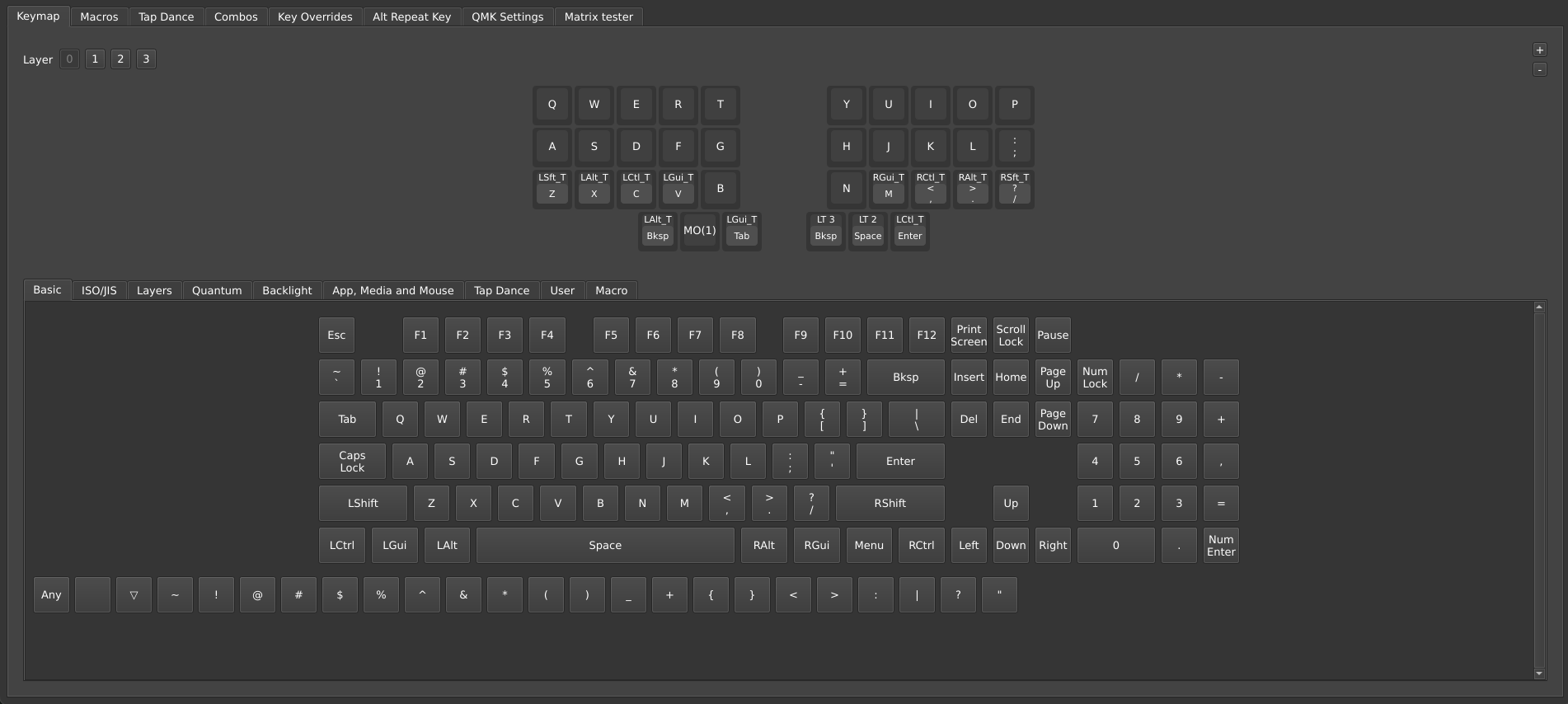
Vial web user interface.
Required Adjustments
Keyboard Layout
I thought my 36 key layout would be completely fine as is, but it was not. Since the thumb cluster was wider, the farthest thumb no longer felt as comfortable or easy to hit for me since it required my hand to stretch across a large distance, especially for combos like CMD+T. For modifiers, I started to use bottom row mods in addition to the thumb clusters, which ended up working quite well.
Desk Ergonomics
Since the keyboard is taller than normal, I started experiencing wrist and shoulder fatigue after a few hours in the first week of using it. Wrist/palm rests also did not help. After some research, I eventually came across advice that changing the height of your desk and/or chair are needed to accommodate the keyboard’s height.
Since I use a floor desk, my desk is the only thing that has height adjustability, so I lowered it 1/2” and found it was a big improvement to my posture. Maybe one day I’ll recess my keyboard into my desk?
I also found that having the two halves closer and slightly angled inwards to be more comfortable than strictly at shoulder width apart. I wonder if it’s something to do with the height of the keyboard and how my forearms aren’t completely parallel with the ground? Either way, the nice thing about having a split is the ability to easily move them around to find the best position. Or as physiotherapists like to say, “the best position is your next position”!
Final Thoughts
One interesting thing about sculpted keyboards is that if the rubber feet are a bit dusty, the keyboard would have a tendency to shift inwards while typing. This is not an issue with flat keyboards since the direction of force is vertically down, whereas here, the force vectors are also horizontal. This can be mitigated by making sure the rubber feet are clean and have good grip, or adding small weights to the case (e.g. with motorcycle wheel balancing weights).
I also noticed how my hands wanted to rest in home row (e.g. the lowest sloped area of the keyboard). In contrast to a typical flat keyboard, where my right hand would sometimes rest one key over on HJKL (because of vim and vim-like keybindings on many apps I use), it didn’t matter as much since my hands could just shift laterally without significantly changing my wrist angle/position. It required some adjustment to train my right hand to really stay on home row and use my forefinger to span the two columns YHB and UJN instead of just one, which I found particularly difficult since reaching over with my forefinger often led to bumping into the tallest thumb key.
The curvature for the ring and pinky fingers were quite comfortable for me, and being able to press the top outermost keys with my pinkies was a nice change.
The thumb clusters could also be a little lower and shifted slightly inward, since the outer key is hard to reach for my (somewhat) smaller hands. But this is getting into specific hand morphology, so YMMV.
All in all, I was quite pleased with how it turned out, and I’ve been daily driving this keyboard for a few weeks now. Unfortunately, building my first keyboard from scratch has opened the Pandora’s box of the desire to build even more keyboards, so time will tell if my journey ends here or continues on…